Before training the defect model, fix the photograph
A defect must remain visible at line speed. Lighting geometry and exposure time determine what evidence an inspection model receives.
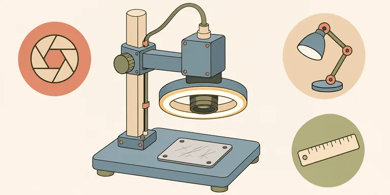
A scratch that disappears into glare is a camera-station problem before it becomes a model-training problem. The software receives the image that the optics produced.
That sounds obvious until a vision project starts collecting thousands of photographs from a setup that changes each afternoon. A model may then have to separate product variation from changes in the photograph. Some of that variation can be removed at the station, which gives the training effort a more useful starting point.
Make the feature visible
A camera records how light reaches its sensor. A different light angle can change which features of a reflective surface become visible. Edmund Optics' darkfield illumination guide explains the use of low-angle illumination for machine vision, with examples involving surface features and reflective materials.
The implication for an inspection project is to test the defect with the intended illumination before collecting a training set. A shallow scratch on reflective metal and a missing hole in a silhouette need different photographic evidence. A setup that produces an attractive picture may still conceal the feature the decision depends on.
I would begin with several acceptable parts and known examples of the target defect. Keep the camera position fixed, then compare a few plausible light arrangements. Record which differences remain visible when the part is rotated within the range the line will allow. This is a suggested test procedure, not a claim that one lamp arrangement works for every product.
The acceptance question is whether a reviewer can identify the required feature consistently in those images. If the photographs are ambiguous, adding labels creates a collection of ambiguous examples. The label cannot restore surface detail that was never recorded.
A moving part has an exposure budget
Basler's image-quality documentation describes the trade-off: longer exposure can brighten an image but increases the risk of motion blur. Raising gain also brightens the image while amplifying noise. These settings affect the evidence presented to the model.
The same physical tension appears in the research paper Learn to See Faster, which studies high-speed capture under limited light. Shorter exposures reduce the time available to collect light. Computational methods can help with particular capture problems, but their measured results do not remove the need to test the actual camera and scene.
Consider an illustrative belt moving at 500 millimetres per second. If the image scale is ten pixels per millimetre, the scene moves across the sensor at 5,000 pixels per second. An exposure of one millisecond allows five pixels of movement during capture. An exposure of one-fifth of a millisecond allows one pixel, under this simplified constant-speed assumption.
These are example values, not a specification for a factory camera. They show why an image captured with a stationary sample can be misleading. The setting that produced a bright photograph on a desk may smear a small feature when the sample moves at production speed.
Lighting intensity, permitted exposure, and the feature size therefore need to be considered together. The installation test should use the intended motion, including the allowed variation in speed. A decision about the lamp cannot be postponed until after the model has been evaluated on still photographs.
Separate the part from changes in the photograph
The MVTec AD 2 benchmark includes test lighting that can differ from training conditions. Its design makes an important production question visible: does a system keep working when acceptable material is photographed differently?
For an installation, I would first identify which differences can be controlled. A rigid mount can constrain camera position. An enclosure can reduce changing ambient light. A documented cleaning method can make it possible to investigate a dirty protective window. These are engineering choices to evaluate locally, not a guarantee that the remaining images will be identical.
Some variation belongs to normal production. A supplier may deliver acceptable parts with a different finish. The inspection method still needs to handle the agreed range. Removing accidental variation at the station makes that material question easier to investigate.
The camera settings belong with the image record. If exposure changes automatically during capture, retaining the effective value helps explain why two frames look different. Basler's exposure documentation describes reading the relevant exposure settings for supported camera families. A reproducible test needs the values actually used, not a remembered default.
Keep a reference capture after installation
Once a station passes its agreed tests, retain representative images with the configuration that produced them. They give a maintenance investigation a concrete comparison after a lens adjustment or lighting replacement.
A useful maintenance question is whether the station can still produce the reference evidence under the permitted operating conditions. If it cannot, the team has a capture problem to resolve before interpreting a change in model scores.
The model can only evaluate the information delivered to it. For a visible defect, the first investment should establish an image in which that defect can be judged at line speed. Training then has a defined observation to work with.